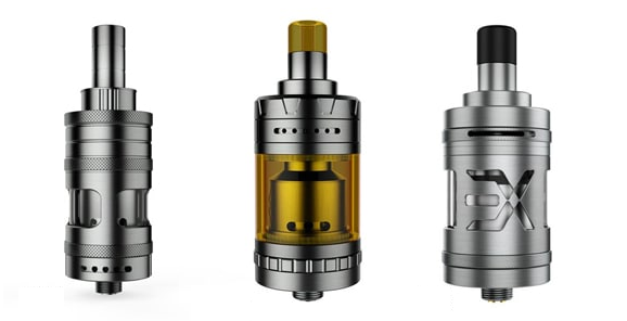
Reminiscent of the little engine that could, only they didn't! ... buuuuuuuuut they can ... with a minor modification.

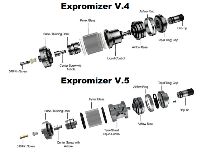
The V5 comes closer to my version of loose MTL than the V4, so lets look at it first;
Some measurement and math on the air flow revealed that the V5 top air flow had a total area, (wide open), of 13.7854 square mm ... DL territory!
The junction between the chamber airflow and deck, a total volume of 4.7124 square mm, (into RDL territory), and;
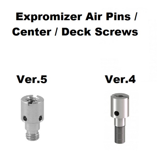
The center screw also has some restrictions at 1mm x 4 = 3.1416 square mm feeding a 1.5mm centre hole with an area of 1.7672 square mm, which in turn feeds the undercoil holes with a volume of 2.3562 square mm.
To correct the center screw bottleneck, and move it to under the coil, we would need enlarge the centre hole of the center screw, to give us an area of at least 2.3562 square mm, which equates to 1.7321mm ... I'll use a 1.8mm drill bit, and err on the side of more air.

Anyhooooo ... on to the V4 ... so here they have a top air flow area, (wide open), of 4.7124 square mm, (roughly a third as much air as the V5).
The junction between the chamber airflow and deck, as with the V5, a total volume of 4.7124 square mm, SNAP ... and;
An undercoil volume of ... wait for it ... 5.0265 square mm ... so where is the problem? ...
Just like the V5 ... It's the flippen "center screw with airhole", which is slightly more restrictive than the V5, at 4 x 1mm, (3.1416 square mm), into a 1.2 mm center hole (1.131 square mm!)
So to "convert" your V4 to a V5, you would need to drill this out carefully to 1.5mm, from 1.2mm, or ... to make it really perform;
Drill it out to 1.8mm as per the V5 modification above.
This would allow a greater "spread" of air at lower air flows, increasing saturation, whilst allowing them to function in the RDL space simply by adjusting the top airflow.

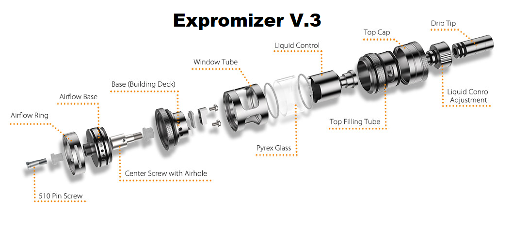
Interesting little factoid ... The Ver.3 had a 2.6mm hole under coil, and was a great MTL AND RDL Atty, until Todd decided in his great broscience / non scientific way, to tell the world that 2.6mm was too big ...
Do these reviewers even know what fluid dynamics is, or bother to take into account ALL other restrictions in an Atomiser, as underneath the deck, underneath the 2.6mm hole, was a 2mm restriction ... yes you guessed it, a flippen "Center Screw with Airhole" ... not to mention that air is being pulled NOT pushed ... that there is a vacuum created when you suck, which is decidedly different from air being pushed into the airflow, anyhoooo ... all this prompted the aforementioned shifts above, which thankfully can be easily corrected, to bring the Expro back into the domain of outstanding.


The V5 comes closer to my version of loose MTL than the V4, so lets look at it first;
Some measurement and math on the air flow revealed that the V5 top air flow had a total area, (wide open), of 13.7854 square mm ... DL territory!
The junction between the chamber airflow and deck, a total volume of 4.7124 square mm, (into RDL territory), and;
The center screw also has some restrictions at 1mm x 4 = 3.1416 square mm feeding a 1.5mm centre hole with an area of 1.7672 square mm, which in turn feeds the undercoil holes with a volume of 2.3562 square mm.
To correct the center screw bottleneck, and move it to under the coil, we would need enlarge the centre hole of the center screw, to give us an area of at least 2.3562 square mm, which equates to 1.7321mm ... I'll use a 1.8mm drill bit, and err on the side of more air.

Anyhooooo ... on to the V4 ... so here they have a top air flow area, (wide open), of 4.7124 square mm, (roughly a third as much air as the V5).
The junction between the chamber airflow and deck, as with the V5, a total volume of 4.7124 square mm, SNAP ... and;
An undercoil volume of ... wait for it ... 5.0265 square mm ... so where is the problem? ...
Just like the V5 ... It's the flippen "center screw with airhole", which is slightly more restrictive than the V5, at 4 x 1mm, (3.1416 square mm), into a 1.2 mm center hole (1.131 square mm!)
So to "convert" your V4 to a V5, you would need to drill this out carefully to 1.5mm, from 1.2mm, or ... to make it really perform;
Drill it out to 1.8mm as per the V5 modification above.
This would allow a greater "spread" of air at lower air flows, increasing saturation, whilst allowing them to function in the RDL space simply by adjusting the top airflow.

Interesting little factoid ... The Ver.3 had a 2.6mm hole under coil, and was a great MTL AND RDL Atty, until Todd decided in his great broscience / non scientific way, to tell the world that 2.6mm was too big ...
Do these reviewers even know what fluid dynamics is, or bother to take into account ALL other restrictions in an Atomiser, as underneath the deck, underneath the 2.6mm hole, was a 2mm restriction ... yes you guessed it, a flippen "Center Screw with Airhole" ... not to mention that air is being pulled NOT pushed ... that there is a vacuum created when you suck, which is decidedly different from air being pushed into the airflow, anyhoooo ... all this prompted the aforementioned shifts above, which thankfully can be easily corrected, to bring the Expro back into the domain of outstanding.

Last edited:


