DIY Battery Charger

Intuthu Kagesi

Proficitis cum eo
LV
24
 
Joined
17/8/20
Posts
3,946
Awards
27
Location
Bedfordview
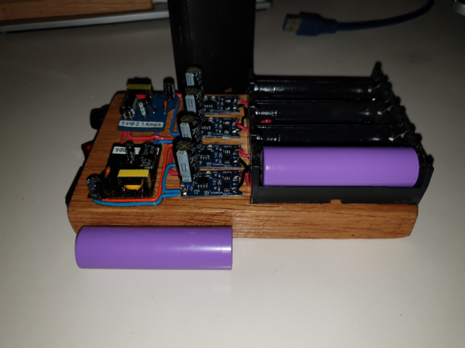
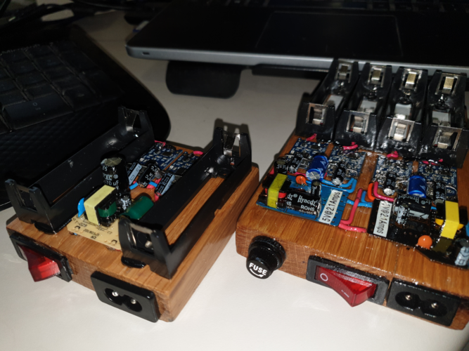
I’ve used the TP4056 a number of times to repair forum members failed Li-Ion Chargers, and decided to build a fast?(ish) charger from scratch with an “Old School” / Steam Punk theme.

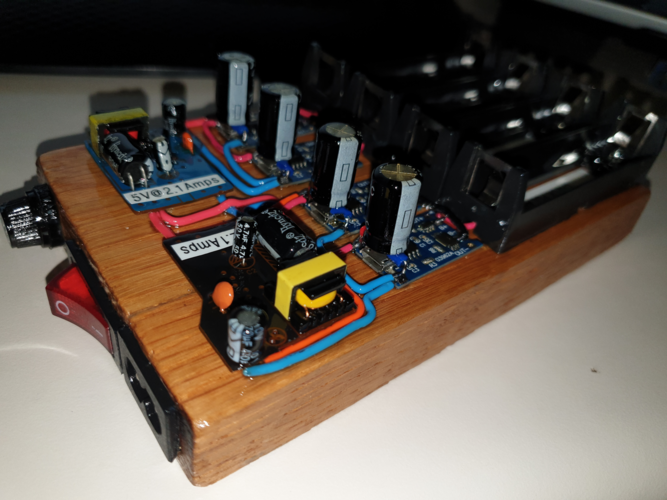
The TP4056 Modules are available from Mantech for a little more than ten bucks, and I added in two “Chinatown“ 2.1 Amp Cell Phone Chargers, (disassembled to maintain the exposed / old school look), a piece of oak, a stove switch, a “figure 8” mains socket, four 18650 battery holders, and a fuse holder, probably adding another fifty bucks to the total project cost.

As this charger has exposed electrical connections, I “hid” most of the 230Volt wiring within the wood, and … only used fireproof silicone insulated wiring, however the exposed boards got a few coats of a clear insulating lacquer for additional safety.

The finished charger did reveal some fairly formidable statistics to …

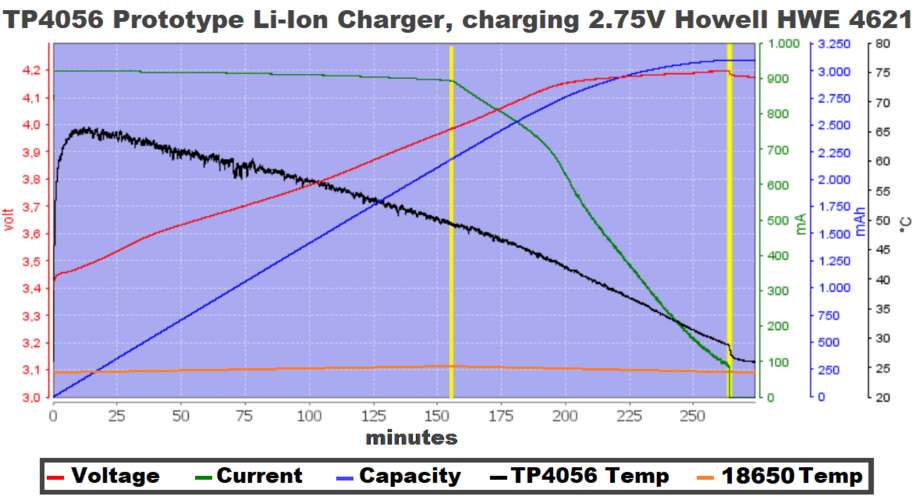
I tested it using, (discharged to 2.75 Volts), Howell HWE4621 Cells, (as I still have their test data), and … the charger does a great Constant Current to Constant Voltage charge, albeit that the changeover from CV to CV is a bit “soft”, (this does increase charge time marginally), however if anything, it’s arguably better for battery longevity. The charger is also a tad below the 1A claimed current spec. coming in at 950mA. The CV voltage however was bang on, at 4.2 Volts, (in spite of the datasheet specifying between 4.137 and 4.263 volts). This chip also uses the industry accepted methodology of 1/10 of the initial charge current as termination current, (confirmed), and … has built in thermal protection.

As everything is exposed, the circuit and the cells remained relatively cool … the physical TP4056 IC did come close to 68 degrees C in the early stages of charging, however this is well within specification, and the cells temperature peaked on a cool 26 degrees C … just as the changeover from constant current to constant voltage occurred.

The TP4056 also has what the manufacturer refers to as a trickle charge feature, which is more of a “resurrect the dead” feature, in that any cell below 2.5Volts is first trickle charged until it reaches 2.5Volts, and then the pre-programmed CC to CV cycle goes ahead.

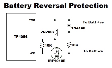
A word of warning … these modules DO NOT have reverse polarity protection, (you don’t put batteries into your charger back to front, do you? :rolleyes:), but … you can add the circuit included below if you want peace of mind.
1650396703124.png

1650396794010.png
1650396886751.png
 
Nice looking charger @Intuthu Kagesi .

What are the caps for across -ve and +ve in?

Like you, I really prefer it with the exposed boards/components. It also helps with heat dissipation although the TP4056 is pretty bulletproof.

I have a feeling that it would scare the heck out of some people. You have protected the AC side to such an extent that it would take a Darwin Award contestant to manage to shock himself. The DC 5V side is pretty tame as you know.

The beauty of your charger is that each cell is charged at 1A, unlike many commercial chargers.
Thanks for that ...

Those are just decoupling caps, a little larger than needed, but they're what I had lying around ... Them cheapie cell phone chargers generate a LOT of spurious harmonics with their half wave rectified, self oscillating inverter design, and one of the TP4056's took exception to em', so I just decoupled all the 4056's.
 
The Bigger the Better......;) This is inspiration to a person like me. I'm no good at woodworking but a 3d printed enclosure should work.
For the record ... my woodworking skills amount to how to burn wood on a braai :giggle:, specifically in that woodwork is more of an art form than a science ... so it was a stretch for me :rolleyes: ... that said, I'd recommend you give it a go ... nothing ventured, nothing gained ;)
 
I think that looks brilliant. I could actually see this with a 3d printed clear box type lid with some vent holes, just to keep little fingers out, like my grandson, oooh ooooh
 
Thanks for that ...

Those are just decoupling caps, a little larger than needed, but they're what I had lying around ... Them cheapie cell phone chargers generate a LOT of spurious harmonics with their half wave rectified, self oscillating inverter design, and one of the TP4056's took exception to em', so I just decoupled all the 4056's.

Thanks. Now I get it :).

Phone chargers are notoriously crap. Good workaround.

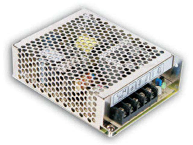
You can also get 5V 12A switching power supplies for a good price. Around R 270. This would still work out cheaper than a brand name charger. With 12A available you could also have more than 4 bays with each one charging at 1A.

1650458736164.png

My 4 bay 2A charger is still working well but isn't nearly as pretty as yours :-(.

I will post pics after I have upgraded it.
 
Thanks. Now I get it :).

Phone chargers are notoriously crap. Good workaround.

You can also get 5V 12A switching power supplies for a good price. Around R 270. This would still work out cheaper than a brand name charger. With 12A available you could also have more than 4 bays with each one charging at 1A.

View attachment 254455

My 4 bay 2A charger is still working well but isn't nearly as pretty as yours :-(.

I will post pics after I have upgraded it.
I look forward to seeing your charger pics too :)

As to the SMPS you posted ... I love those encased SMPS', and you can't build one for the same price either ...
They have a 12V 5 Amp version for under R100 that you can change the resistor in series to the voltage adjustment pot, (dropping it by 1/3), to extend the output up to 15V, (remembering that max current also drops to 4A at 15V)
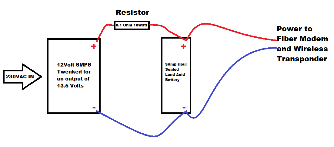
You can then set the output to 13.6 Volts and ... with a 0.1 Ohm 20W resistor in series with a 9AHr 12 Volt Sealed Lead Acid Battery, and it now becomes a cost effective Fibre / Wireless UPS :)
 
Last edited:
@Intuthu Kagesi

The UPS sounds like a good option.

Where did you see the 12V 5A power supply for under R 100? It sounds like a real bargain. At that price, I would get one to make a 4 bay 1A charger with TP4056s..

I recently won an auction for three power supplies on Bidorbuy. 2 X 30A 12V and 1 X 20A 12V. I am going to use one for my next 2A charger.
I'm not sure if you have "Mr Panda" in Cape Town :wondering: ... They have three stores that I know of in the Greater JHB area, Boksburg, Bruma and Randburg, and they stock the 5 and 12 Volt units in 2, 5, 10, and 20 Amps.
 
I look forward to seeing your charger pics too :)

As to the SMPS you posted ... I love those encased SMPS', and you can't build one for the same price either ...
They have a 12V 5 Amp version for under R100 that you can change the resistor in series to the voltage adjustment pot, (dropping it by 1/3), to extend the output up to 15V, (remembering that max current also drops to 4A at 15V)
You can then set the output to 14.6 Volts and ... with a 0.1 Ohm 20W resistor in series with a 9AHr 12 Volt Sealed Lead Acid Battery, and it now becomes a cost effective Fibre / Wireless UPS :)
Do tell us more.... How exactly do you connect the battery? To the output side in parallel with the load?


Sent from my vivo 2006 using Tapatalk
 
Do tell us more.... How exactly do you connect the battery? To the output side in parallel with the load?


Sent from my vivo 2006 using Tapatalk
A picture paints a thousand words ;)
This circuit will replace the existing 12Volt PSU(s) you have.
A typical Fibre Modem and Wireless Transponder will draw some 1 to 1.2Amps, so a 9AHr battery should provide you with 4 hours of backup and take the battery to just below 50%, (It's not a good idea to drop a Lead Acid Battery charge below 30%!)
1650482369054.png
/
 
Ah, Got you. I think I had a slight glitch in my matrix..... I think I need to take a road trip to Mr Panda.
 
... and then the mini was born :rolleyes:
In a bored moment in between playing Uber to my Grandchildren, scavenged some of the spares I had lying around, and knocked this lil' number up earlier today ... a two cell 18650 1Amp / cell Charger. Like it's "brother", all the 230Volt wiring is concealed within the wood base, leaving the 5 and 4.2 Volt circuitry exposed, (albeit electrically insulated), for visual appeal.

1652284907934.png
 
... and then the mini was born :rolleyes:
In a bored moment in between playing Uber to my Grandchildren, scavenged some of the spares I had lying around, and knocked this lil' number up earlier today ... a two cell 18650 1Amp / cell Charger. Like it's "brother", all the 230Volt wiring is concealed within the wood base, leaving the 5 and 4.2 Volt circuitry exposed, (albeit electrically insulated), for visual appeal.

View attachment 255687

Time to activate your website to take orders... well done Uber Oupa!
 
I like the fact that the battery bays are spaced further apart in the mini version. I struggle to get batteries out of a full four-bay charger.

The exposed circuitry wouldn't worry me at all. If you were to sell them it may be an issue but after all, commercial chargers have some exposed circuitry. The charger terminals are "live" if bridged.
Thanks for that ... I'm old school, and we didn't print warning signs like "don't stick yer friggen finger in the plug socket", and "don't lean over the banister" ... we jus' let stupid people cull themselves :-D
Wrt selling any of my tinkering(s) ... I'm over commercial ventures for now, and won't be selling any in a hurry, however I do use both the TP4056 and 5100 boards to repair charge circuitry in various LI-Ion devices for forum members, (not in "exposed format" as I've done for the two in this post tho'), and then to the battery removal challenge ... a shortish piece of cloth strip, (not unlike a lot of mods use), under the cell(s) resolves the issue rather nicely ;)
 
Back
Top