Just checking i have built 2 already and 3rd one still to be built. Mine i left every thing together, i use my doge as it pushes the pin the deepest, put flux in the center pin and soldered the wire before i put it in the hole, just used the small solder bit to heat up till the solder took properly. Find its the best way. Just dont solder the wire on the outer positive ring as u will loose alot of voltage because you will basically use the small spring as a positive supply thenI have completely removed the positive pin from the 510. If you further strip it down you can remove the actual pin from the white delrin plastic (there is also a spring, and a TINY Oring to be removed - make sure you don't lose these.). I am planning to solder the positive pin with one wire, then reassemble the positive pin, and then insert it into the 510. The positive pin wire will then be soldered to the left positive post on the battery sled (I have a wire running as a jumper inbetween the first and second positive posts of the sled). I am aiming to use the left post as the center meeting point for all positive wires.
I am a little worried that the MOSFET 'chip' - (just pulling @johan's leg) got too hot while soldering, but hopefully it will survive the process.
Navigation
Install the app
How to install the app on iOS
Follow along with the video below to see how to install our site as a web app on your home screen.

Note: this_feature_currently_requires_accessing_site_using_safari
More options
You are using an out of date browser. It may not display this or other websites correctly.
You should upgrade or use an alternative browser.
You should upgrade or use an alternative browser.
DIY Mod build Q&A.
- Thread starter TylerD
- Start date

Just checking i have built 2 already and 3rd one still to be built. Mine i left every thing together, i use my doge as it pushes the pin the deepest, put flux in the center pin and soldered the wire before i put it in the hole, just used the small solder bit to heat up till the solder took properly. Find its the best way. Just dont solder the wire on the outer positive ring as u will loose alot of voltage because you will basically use the small spring as a positive supply then
I dont recommend this as you stand a good chance of melting the insulator. Its best to just solder the pin when seperate
I dont recommend this as you stand a good chance of melting the insulator. Its best to just solder the pin when seperate
Yes I agree, while Sean's method does work, it is not noob friendly, or very forgiving for those who take time to solder a connection right.
For those of you who are not that comfortable with soldering, I would strongly advise stripping the pin down completely.
Now if I could just work out how the pin goes back together...
PS @eviltoy I see you are still an active anti-Ratava proponent. Good on you man, I am proud
Ok I am in need of some assistance from the electrically minded folks...
I finished assembly of the wiring rig, got everything soldered into place, hook it up to the multi meter with a battery (one) in place. Fire the button and... zero voltage.
I go into diagnostic mode with the multi meter checking both for continuity, as well as voltage being carried from battery sled to the mosfet/switch/510. I start removing heatshrink to check for dry/disconnected solder joints. Everything seems fine. I repeat checks: from positive terminal of the battery sled to switch (fine), then check continuity of each lead running to the mosfet (again fine), check the actual switch itself (fine). Check that both the negative and positive parts of the 510 are properly installed, and the multimeter beeps to confirm there is a circuit between the terminals and the respective bits (checked both the outside of the 510 and the inside where the leads connect. It appears the connections to the 510 are right. Again all seems fine.
The only thing that is not registering any continuity is the resistor mounted across the left outermost and right outermost legs of the mosfet. So I have two questions:
1) Am I correct in thinking that the resistor should still beep to show continuity if it is working properly?
2) Is it possible the issue itself is with the mosfet, and could it have overheated during the soldering process?
Any further suggestions as to what I could do would be great! I am now beginning to remember why I previously found assembling any kind of electrical components to be a real PITA!
Stick an atty on does it fire
Nope I did try that as well. Atty is as dead as a door nail as well
Pictures please. If mosfet was fried it usually autofires
I checked online. A resistor won't necessarily beep when tested. It depends on its resistance

I am busy de soldering the mosfet.
How would one know if it is stuffed?
I will agree to disassemble to solder if u are a amateur in soldering. The way i work i heat the wire up and not the actual pin due to the chance of melting the plastic. Once solder starts flowing and hits that flux it gets right in there and it will not come out. But each person has he's preferred way to do thingsI dont recommend this as you stand a good chance of melting the insulator. Its best to just solder the pin when seperate
Dev get pic up and the way it was wired so we can see what went wrongI checked online. A resistor won't necessarily beep when tested. It depends on its resistance
I am busy de soldering the mosfet.
How would one know if it is stuffed?
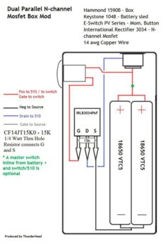
Ok so I have stripped (desoldered) everything from the MOSFET.
Maybe I misunderstood the MOSFET labelling? I went on the following basis:

I figured that the Source was the source, because of the S D printed on the component (check the fourth arrow above). Maybe this was incorrect?
For what it is worth (absolutely nothing) here is the existing installation

The wire at the bottom is the negative (S), the one sticking out on the left hand side (just by the switch) is connected to the 510 negative (D). As things are I removed to wires from the MOSFET, which you cannot see above. The one is the G (connects to the switch) and the second is the positive terminal to other point on the switch
Maybe I misunderstood the MOSFET labelling? I went on the following basis:
I figured that the Source was the source, because of the S D printed on the component (check the fourth arrow above). Maybe this was incorrect?
For what it is worth (absolutely nothing) here is the existing installation
The wire at the bottom is the negative (S), the one sticking out on the left hand side (just by the switch) is connected to the 510 negative (D). As things are I removed to wires from the MOSFET, which you cannot see above. The one is the G (connects to the switch) and the second is the positive terminal to other point on the switch
Last edited:
Dev which area do stayOk so I have stripped (desoldered) everything from the MOSFET.
Maybe I misunderstood the MOSFET labelling? I went on the following basis:
View attachment 28928
I figured that the Source was the source, because of the S D printed on the component (check the fourth arrow above). Maybe this was incorrect?
For what it is worth (absolutely nothing) here is the existing installation
View attachment 28929
The wire at the bottom is the negative (S), the one sticking out on the left hand side (just by the switch) is connected to the 510 negative (D). As things are I removed to wires from the MOSFET, which you cannot see above. The one is the G (connects to the switch) and the second is the positive terminal to other point on the switch
I am in the north of JHB
Is this the same MOSFET as the one in the kit?
http://za.rs-online.com/web/p/mosfet-transistors/6887204/
@SEAN P have I correctly identified the legs on the MOSFET?
Is this the same MOSFET as the one in the kit?
http://za.rs-online.com/web/p/mosfet-transistors/6887204/
@SEAN P have I correctly identified the legs on the MOSFET?
Basically the same. If u need help let me know I will gladly assist u. If mofset is gone then i can grab u one and install for u. Bot from what i can make out wiring could be the problemI am in the north of JHB
Is this the same MOSFET as the one in the kit?
http://za.rs-online.com/web/p/mosfet-transistors/6887204/
@SEAN P have I correctly identified the legs on the MOSFET?
Paulie hows urs treating u?")
So far good Sean
I have 3 box mods (hammond) and more incomming lol I do wish i had the skills to build it myself but i know it would end bad hahaGet urself a kit we sit down and go thru it together. Best way to learnSo far good Sean
Ok so I have stripped (desoldered) everything from the MOSFET.
Maybe I misunderstood the MOSFET labelling? I went on the following basis:
View attachment 28928
I figured that the Source was the source, because of the S D printed on the component (check the fourth arrow above). Maybe this was incorrect?
For what it is worth (absolutely nothing) here is the existing installation
View attachment 28929
The wire at the bottom is the negative (S), the one sticking out on the left hand side (just by the switch) is connected to the 510 negative (D). As things are I removed to wires from the MOSFET, which you cannot see above. The one is the G (connects to the switch) and the second is the positive terminal to other point on the switch
From my basic electronics knowledge and I do mean basic, MOSFET`s are generally configured as Gate, Drain, Source from left to right looking at the device front on (side with the markings). Multimeters that I’ve used in the past will only register continuity if the resistance is below 100 ohms. I don’t think that the Gate-Source resistor is less than 100 ohms. From the information provided it seems as though you’ve swapped the Gate and Source connection around. As best as I can make out your MOSFET is a IRLB 3813. If so heres a link to the datasheet.
http://www.irf.com/product-info/datasheets/data/irlb3813pbf.pdf
Get urself a kit we sit down and go thru it together. Best way to learn
Not likely
@Paulie spends most of his time on a different kind of DIY, and he's quite good at that
Sounds like a planGet urself a kit we sit down and go thru it together. Best way to learn
But ill leave the diy hardware to you guys im more of a juice diy fan
Lol yeah juice Diy is more my thing
Guys we agreed that Selfies/DIY/'alone time'/self service or whatever you wish to call it, we don't need to discuss it here, even if Paulie is "quite good" at it.
Ok so, with some assistance from @SEAN P and @Blu_Marlin I have put away this project for the night. It's time for some Clash of Clans.
I have ordered two new MOSFETs and some other bits and pieces I found online. Will take about a week to deliver. In the meantime I will be trying the build again tomorrow or wednesday, and maybe I can get it to work.

Similar threads
- Replies
- 0
- Views
- 251
- Replies
- 1
- Views
- 3K
- Replies
- 0
- Views
- 2K
- Replies
- 2
- Views
- 1K