An Idea, And If, Some Assistance Required.

I dont quite know how the numbers would stack up. I firmly believe its a fantastic idea, but I cant decide where the lower limit should be.
Unloaded, I would say 3.6v is a battery I would consider putting back on charge.
loaded? as mentioned above, it really does depend on the load. A 0.5ohm coil at 16w or so is 2.8volts. I tended to vape around there on a sig100. So if that is the lower range, and members here want 3.4v or 3.7v then it'll be tough to design something static to cater for all users. Perhaps a small variable resistor would do the job...vape till you arent happy anymore, then set the pot such that the light changes and that is your setting. Pot range for light to go from red to green would be somewhere from 2.8v to 3.6v. Dirty contacts arent an issue, but different cells will drop a different amount when fired, so...ja...a variable resistor pls so we can set our own. You get those small surface mount ones that you need an itty-bitty screwdriver to adjust.

Thanks for your comments and I do agree, but as I explained to a poster above; "I've learned over the years to NOT provide the end-user with an adjustable pot (especially surface mount pots), they WILL break it".
 
the little pager motors would work..they have an offset weight to create vibration. Silent enough not to distract anybody, and the buzzing in your mod will alert you.
 
Seems like a lot of trouble all this.. Get a Regulated Mod LOL
:mask:
 
I love the idea @johan and as a Neonaut I'm still getting to grips with using a device without a battery indicator - although using the amount of juice as an indicator is pretty accurate, but when swapping bottles halfway through one I do get very confused ;)

I would definitely go for one of these, as per your original description - simple but effective design, well done :clap:

Edit: I also change the battery at around 3.7V (no load).
 
@johan put me on the list as well. The only thing that i would say is instead of a red and green led . Why not just a green or just a red . If green go out you know to change battery or no green and only red that comes one when flat .

Personally i would prefer only a red that comes on when flat seeing that when i drive at night it will be very annoying if the green comes on every time a vape .
 
Hi @johan

Great to see the makings of another "@johan" doohickey!

When I change batteries, my battery generally measures around 3.7V (when taken out of the Reo). That seems to be the point at which I prefer to switch to a new battery.

If it helps you, I have done voltdrop tests across all my Reos on a few occasions. My coil resistances vary from about 0.5 to 1.0 ohms. The voltdrop measured under load (at the coil posts when firing, with a wicked juice) has always varied between 0.20 V and 0.30 V. I think I have gotten a 0.18V once, but its usually around 0.25V. This has been using Efest purple 18650 2500 mah flat tops and Efest red 18490 1100 mah nipple tops all of the same age and approximately the same number of charge/drain cycles each. I did one or two tests when all my kit was fairly new and another one about 3 or 4 months ago and another one a few weeks ago. The voltdrop outcomes have been similar on all occasions.

So if you want a lower cutoff under load to mimic the 3.7V (outside reading) I like to change batts at, I would say 3.4 to 3.5V is the region for your device's red light. Probably 3.5V to err on the side of caution.
 
@johan put me on the list as well. The only thing that i would say is instead of a red and green led . Why not just a green or just a red . If green go out you know to change battery or no green and only red that comes one when flat .

Personally i would prefer only a red that comes on when flat seeing that when i drive at night it will be very annoying if the green comes on every time a vape .

Thanks for your comments, I think we are a few already that only requires attention only when the battery needs to be replaced. I will design an option in to have either or.
 
Hi @johan

Great to see the makings of another "@johan" doohickey!

When I change batteries, my battery generally measures around 3.7V (when taken out of the Reo). That seems to be the point at which I prefer to switch to a new battery.

If it helps you, I have done voltdrop tests across all my Reos on a few occasions. My coil resistances vary from about 0.5 to 1.0 ohms. The voltdrop measured under load (at the coil posts when firing, with a wicked juice) has always varied between 0.20 V and 0.30 V. I think I have gotten a 0.18V once, but its usually around 0.25V. This has been using Efest purple 18650 2500 mah flat tops and Efest red 18490 1100 mah nipple tops all of the same age and approximately the same number of charge/drain cycles each. I did one or two tests when all my kit was fairly new and another one about 3 or 4 months ago and another one a few weeks ago. The voltdrop outcomes have been similar on all occasions.

So if you want a lower cutoff under load to mimic the 3.7V (outside reading) I like to change batts at, I would say 3.4 to 3.5V is the region for your device's red light. Probably 3.5V to err on the side of caution.

Thanks for your input I really do appreciate it. 99% of all Li-ion and Li-po batteries are safe down between 2.5Vmin and 3.0V according to various data sheets. I personally think and on load detection voltage round 3.2 to 3.5V should cater for most (some of us have quite long toots ;)).
 
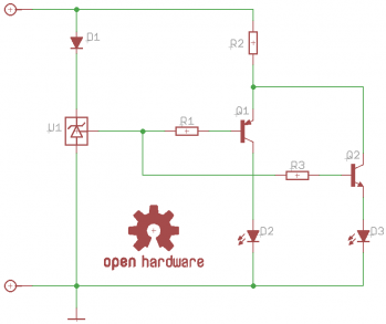
Been looking at some components to use, and at the same time to keep it as simple-stupid-possible. This is the first idea, utilizing an industry standard voltage supervisory IC (Texas Instruments: TPS3809K33) mainly used for DSP's and processor based systems.

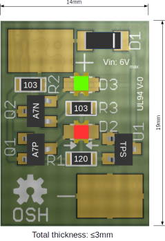
As said previously it will be an "Open Hardware" design (CERN Open Hardware License). Here is the proposed schematic and a quick graphic of the pcb layout. I don't have access to a Reo mini and it will be appreciated if someone can confirm whether a 14mm wide pcb will fit behind the juice bottle on same?

SCH.png

GRPHC.png
PS: Any other techies on this forum?, you are welcome to chime in (schematic, layout, B.O.M available for free, just send me a pm), after all its OSHW.
 
Nice neat design!

Out of curiosity... Does the zener not require a voltage divider resistor network to set the voltage?
Circuit design is not my field of expertise, I've never even worked with a 3 pin zener so interested to understand the operation. My understanding was that it requires a resistor network to determine its bias voltage?

Shane its not a zener diode as such, its a "voltage supervisor" integrated circuit (IC) and in essence it works as follows:

During power-on, RESET (the 3'rd pin) is asserted when the supply voltage becomes higher than 1.1V on pin 1 (pin 2 referenced to ground). Thereafter, the supervisory circuit monitors supply voltage and keeps the RESET pin active as long as the supply voltage remains below the threshold voltage. An internal timer delays the return of the output to the inactive state (high) to ensure proper system reset. The delay time, 200ms, starts after the supply voltage has risen above the threshold voltage. When the supply voltage drops below the threshold voltage, the output becomes active (low) again. No external components are required. All the devices of this TPS8902 family have a fixed sense-threshold voltage set by an internal voltage.

Hopes this explains it.
 
my dad would probably have been the perfect guy to help with this, but he is not a smoker / vaper, and he is PC illiterate... it's a good thing if I can get him to bloody read his mail, LOL

Other than that, he is in the two way radio business and building / modifying all sorts of weird and wonderful stuff.. but urg, just trying to get him onto this forum, and read never mind type something would be a mission!! LOL... i'm sure you will probably get all the help you need :)

One thing I need to mention.... with the RC heli's you actually get a little device that plugs in on your batteries ( usually use it when you suspect a degrading performance battery, to make sure the battery keeps withing expected limits) it simplu plugs in on your battery, and monitors the voltage on the battery, you can set the required voltage and the thing has a light and an VERY loud alarm ( you need to hear it while your chopper/drone/plain is flying, so trust me this thing is loud!!!! but i'm sure you can disable (solder the horn off) and use it for what you are trying to do here... plus it has the added benefit of allowing you to choose the voltage it witch it alerts you...

on this note, be warned, as with the heli's while doing some 3D flying and the motor working a bit harder, it does dip below the set voltage but then again the voltage normalizes after, the same would happen with you using it on your mod.. it will dip probably depending on your build to below the set voltage, showing the alarm, but will normalize again after... so when the normalized voltage is reach while not firing, then you need to change your battery... not before or you will end up with a bunch of half used batteries when you get to your charger... :) (remember, your battery charges up to 4.2 volts but it's nominal voltage (where you will be using it for the longest time and it's comfort range) is 3.7 Volts (well that is for most of the 18650's and 26650's i have seen)

Below is a picture of the device i'm talking about... if memory servers the battery checker is in the range of 50 - 80 Rands... so not a train smash... perhaps take a look at these devices before going to far into creating your own one...

Let me know what you think

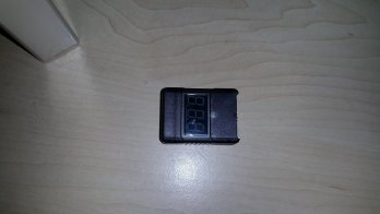
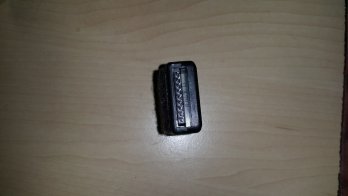
The tester that I have comes in a small casing as you can see, i'll give you the different angles, the top
20150428_191527.jpg
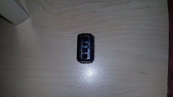
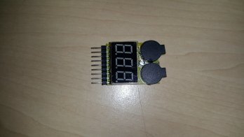
The side with the horns..
20150428_191533.jpg
The side with the connectors (works from one cell batteries up to 9)
20150428_191538.jpg
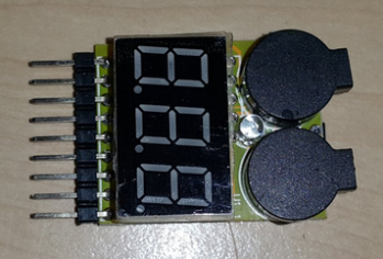
Image of the top side, removed from it's casing
20150428_191556.jpg
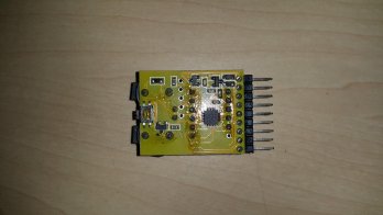
and the bottom of the tester, when removed from the casing
20150428_191602.jpg
In the video demonstrating it working.. you will note that it counts from cell one and it's voltage right up to cell 6 with it's voltage and then it has "all" this is because this is a 6 cell battery... the less cells the battery has then it only shows those cells...

Check it out and see if this can possibly already fulfill your needs... and with an added bonus of a nice LCD display, plus, you can even use it on box mods with more cells, so it will even show you that :)
 
Shane its not a zener diode as such, its a "voltage supervisor" integrated circuit (IC) and in essence it works as follows:

During power-on, RESET (the 3'rd pin) is asserted when the supply voltage becomes higher than 1.1V on pin 1 (pin 2 referenced to ground). Thereafter, the supervisory circuit monitors supply voltage and keeps the RESET pin active as long as the supply voltage remains below the threshold voltage. An internal timer delays the return of the output to the inactive state (high) to ensure proper system reset. The delay time, 200ms, starts after the supply voltage has risen above the threshold voltage. When the supply voltage drops below the threshold voltage, the output becomes active (low) again. No external components are required. All the devices of this TPS8902 family have a fixed sense-threshold voltage set by an internal voltage.

Hopes this explains it.

Aaaah Ok, that makes sense. Thanks for the explanation.
 
Just an idea... How much extra would it cost to encapsulate the pcb in resin? Just concerned about juice leakage
 
@johan love your design, must confess my very limited limited knowledge is for a higher current. I was thinking about the LED colors, is the green and red color set i stone or will you allow for options later? I think blue will look awesome with the black Reo and then red to tell you it is time :)
 
my dad would probably have been the perfect guy to help with this, but he is not a smoker / vaper, and he is PC illiterate... it's a good thing if I can get him to bloody read his mail, LOL

Other than that, he is in the two way radio business and building / modifying all sorts of weird and wonderful stuff.. but urg, just trying to get him onto this forum, and read never mind type something would be a mission!! LOL... i'm sure you will probably get all the help you need :)

One thing I need to mention.... with the RC heli's you actually get a little device that plugs in on your batteries ( usually use it when you suspect a degrading performance battery, to make sure the battery keeps withing expected limits) it simplu plugs in on your battery, and monitors the voltage on the battery, you can set the required voltage and the thing has a light and an VERY loud alarm ( you need to hear it while your chopper/drone/plain is flying, so trust me this thing is loud!!!! but i'm sure you can disable (solder the horn off) and use it for what you are trying to do here... plus it has the added benefit of allowing you to choose the voltage it witch it alerts you...

on this note, be warned, as with the heli's while doing some 3D flying and the motor working a bit harder, it does dip below the set voltage but then again the voltage normalizes after, the same would happen with you using it on your mod.. it will dip probably depending on your build to below the set voltage, showing the alarm, but will normalize again after... so when the normalized voltage is reach while not firing, then you need to change your battery... not before or you will end up with a bunch of half used batteries when you get to your charger... :) (remember, your battery charges up to 4.2 volts but it's nominal voltage (where you will be using it for the longest time and it's comfort range) is 3.7 Volts (well that is for most of the 18650's and 26650's i have seen)

Below is a picture of the device i'm talking about... if memory servers the battery checker is in the range of 50 - 80 Rands... so not a train smash... perhaps take a look at these devices before going to far into creating your own one...

Let me know what you think

The tester that I have comes in a small casing as you can see, i'll give you the different angles, the top
View attachment 26164
The side with the horns..
View attachment 26166
The side with the connectors (works from one cell batteries up to 9)
View attachment 26168
Image of the top side, removed from it's casing
View attachment 26169
and the bottom of the tester, when removed from the casing
View attachment 26170
In the video demonstrating it working.. you will note that it counts from cell one and it's voltage right up to cell 6 with it's voltage and then it has "all" this is because this is a 6 cell battery... the less cells the battery has then it only shows those cells...

Check it out and see if this can possibly already fulfill your needs... and with an added bonus of a nice LCD display, plus, you can even use it on box mods with more cells, so it will even show you that :)


Thanks for your input, yes I know these types and have about 20 of them in clear heatshrink (so if you need some just let me know - pic below). It would be wonderful if your dad can chime in.

Regarding the voltage "dipping"; exactly why I select the TPS8902 family of IC's - build in 200ms delay and the alert will only come on when the battery under load (dipping state), gets below i.e +/- 3.2V (I still need to do some tests to determine the average "dipping" voltage). The "idea" circuit is only active when the firing button is pressed.

Screenshot - 28042015 - 19:36:53.png
 
@johan love your design, must confess my very limited limited knowledge is for a higher current. I was thinking about the LED colors, is the green and red color set i stone or will you allow for options later? I think blue will look awesome with the black Reo and then red to tell you it is time :)

I think once the design is finalized we should do a poll and decide, but at this stage Red & Green are only used for example purposes - we can do basically any of the following colors:
  • Red
  • Green
  • Blue
  • White
  • Yellow
  • Amber
Those that have access to soldering irons/stations, its easy to remove and replace with another color LED. PS: SMD's (surface mount devices) are easy to de-solder/solder with an ordinary soldering iron and you don't need fancy equipment.
 
Will hot glue work?

Hot snot will work kimbo.

I intend, if the idea comes to fruition, to conformal coat the pcb. We use that in the industry to protect pcb's against moisture, corrosion etc. In fact the pcb (and all the components) are waterproof once properly conformal coated.

Epoxy is expensive and you need a little mould plus vacuum pump to do correctly.
 
Just an idea... How much extra would it cost to encapsulate the pcb in resin? Just concerned about juice leakage

I intend, if the idea comes to fruition, to conformal coat the pcb. We use that in the industry to protect pcb's against moisture, corrosion etc. In fact the pcb (and all the components) are waterproof once properly conformal coated. Epoxy is expensive and you need a little mould plus vacuum pump to do correctly.
 
Back
Top