An Idea, And If, Some Assistance Required.

johan

* * * * *
VIP
LV
48
 
Joined
31/1/14
Posts
9,336
Awards
41
Location
Ireland
What
I've been contemplating to make a small indicator circuit for quite some time.

Reason
Now the "need" originates mainly from my social behavior at certain times. I've experienced too many times on a day/night out, getting so involved with conversations and too much "cold drinks" (like Oros), that I vape a battery beyond its safe discharge level without consciously noticing it.

Under normal conditions I would immediately notice it, and when measured, the battery would've discharged to round about 3.8V (roughly after 3ml of e-juice on a standard Reo bottle).

How
Apologies for all the waffle above. Now, what I intend to do, is design a simple circuit to emit a green light, if the battery's voltage is above x-voltage (when I press the firing button) and emit a red light when the battery voltage is below y-voltage (when I press the firing button). This little circuit should not be bigger than: width: 15mm x hight: 30mm x thick: 3mm. It will be easy to stick it behind the Reo or Kui juice bottle and emit the relevant colors. The circuit will draw less than 10mA when the fire button is pressed and no current when the fire button is not pressed. Connection would be easy; 1 x thin black wire tugged underneath the negative battery spring and 1 x thin red wire connected to the centre pin or leaf spring (positive side).

Why
Why do I need your assistance? The design is not the issue, but to get the pcb's made and purchasing small quantity of components are a costly affair, if I only do one/two for myself. If there is enough interest in something like this, what would you prefer to be the minimum discharge voltage to trigger the red emitting light? 3.0V or 3.2V or 3.5V etc.
 
I'm in! Tell me what you need @johan! This could be a chicken dinner for Reonauts all over the planet!

PS What are the chances of having a deluxe version that shines blue when firing. Will look so kewl in an SL when is hide in a cupboard and vape! ;-)
 
I'm in! Tell me what you need @johan! This could be a chicken dinner for Reonauts all over the planet!

PS What are the chances of having a deluxe version that shines blue when firing. Will look so kewl in an SL when is hide in a cupboard and vape! ;-)

It can be any color you like as long as its either: white, red, green, violet, or blue. What I need now is a poll of at which voltage the "danger" light must come on?
 
It can be any color you like as long as its either: white, red, green, violet, or blue. What I need now is a poll of at which voltage the "danger" light must come on?

Sweet! 3,7V for me please.
 
I would also be interested in one of these

3.7 would work, although i change batteries at 3.8
 
I would also be interested in one of these

3.7 would work, although i change batteries at 3.8

Riaz I also change battery round 3.8V, measured without load (coil in circuit). This circuit's main purpose will be to indicate "low" discharged voltage while load (coil in circuit) is connected. Some brands of batteries and especially aging batteries, will much quicker reach that threshold (i.e 3.8V) when the firing button is pressed, although it might measure 3.85V when no load is connected. Hope it makes sense.
 
Riaz I also change battery round 3.8V, measured without load (coil in circuit). This circuit's main purpose will be to indicate "low" discharged voltage while load (coil in circuit) is connected. Some brands of batteries and especially aging batteries, will much quicker reach that threshold (i.e 3.8V) when the firing button is pressed, although it might measure 3.85V when no load is connected. Hope it makes sense.
Makes perfect sense @johan

I have to take my batteries out to check the voltage, so with this contraption is will make things a whole lot easier.
 
Excellent idea Ohm Johan. I too think 3.7v is good, although, I have to say that I immediately notice when my battery is around 3.6v as my vape change considerably in temp and taste. That's how I know it's time for a battery change. Also, by then my bottle is almost empty and I then squonk the last of the juice up the tube and change the battery :)
 
3.7v sounds great @johan. And I would take a couple of these things to help make up the MoQ
 
I would be most interested for sure.
 
Riaz I also change battery round 3.8V, measured without load (coil in circuit). This circuit's main purpose will be to indicate "low" discharged voltage while load (coil in circuit) is connected. Some brands of batteries and especially aging batteries, will much quicker reach that threshold (i.e 3.8V) when the firing button is pressed, although it might measure 3.85V when no load is connected. Hope it makes sense.
My question flows from this: I usually change my battery between 3.7 and 3.8V as measured outside the device on your doohickey. Will the 3.7V light on your indicator be the same as this outside measurement? In other words, I would like the red to go on at the 3.7V (more or less) as if measured not under load.
 
My question flows from this: I usually change my battery between 3.7 and 3.8V as measured outside the device on your doohickey. Will the 3.7V light on your indicator be the same as this outside measurement? In other words, I would like the red to go on at the 3.7V (more or less) as if measured not under load.

Andre that is not possible as no 2 batteries are exactly the same.

To illustrate: If I measure the battery without pressing the fire button (no load) and it reads ie: 4.15V, now when I press the fire button, it will read a lower voltage while current is drawn from the battery (ie: 4.00V). The difference between a no-load voltage measurement and measurement with load (pressing the fire button) varies from battery to battery and different coil resistance will also influence that difference. The lower the coil resistance, the bigger the difference will be.

The main function of this idea is to prevent discharging the battery below a safe low discharged voltage value. The measurement of battery is also only active while pressing the fire button. - I hope it makes sense.
 
Last edited:
@johan I'm in, 3.7v pls..and i'll take two of them (one for my incoming reo...and a spare for the next reo i buy)....
 
LOL, its not even been designed yet - only an idea at this stage.
No issues with that on myside... just means i'm on the list early... lol.
Fantastic idea though... will send you a pm
 
Andre that is not possible as no 2 batteries are exactly the same.

To illustrate: If I measure the battery without pressing the fire button (no load) and it reads ie: 4.15V, now when I press the fire button, it will read a lower voltage while current is drawn from the battery (ie: 4.00V). The difference between a no-load voltage measurement and measurement with load (pressing the fire button) varies from battery to battery and different coil resistance will also influence that difference. The lower the coil resistance, the bigger the difference will be.

The main function of this idea is to prevent discharging the battery below a safe low discharged voltage value. The measurement of battery is also only active while pressing the fire button. - I hope it makes sense.
Makes perfect sense, thanks. Fact is, the measurement under load will be less the the measurement with no load. I think most of us change batteries at around 3.7V - as measured with no load. If this is true, seems to me we should go for the red light at something lower than the proposed 3.7V above to get nearer to the real world situation. Maybe 3.5 or 3.6V?
 
I agree @Andre, I will do some measurements at some stage with different batteries and different coil resistances and see what is a mean average to work from, but my guess at this moment in time is closer to 3.3V under load.

Maybe if there are some other members that would like to play along, they can post their measurements here as well when they feel/taste that a battery needs to be replaced, ie:

Battery Brand:
Coil resistance:
Battery voltage without firing:
Battery voltage while firing:
 
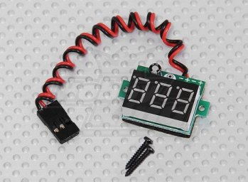
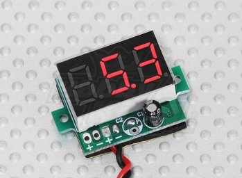
Dimensions: 24mmx20mmx12mm
 

Attachments

  • V-Meter 2.jpg
    V-Meter 2.jpg
    49.5 KB · Views: 22
Back
Top